
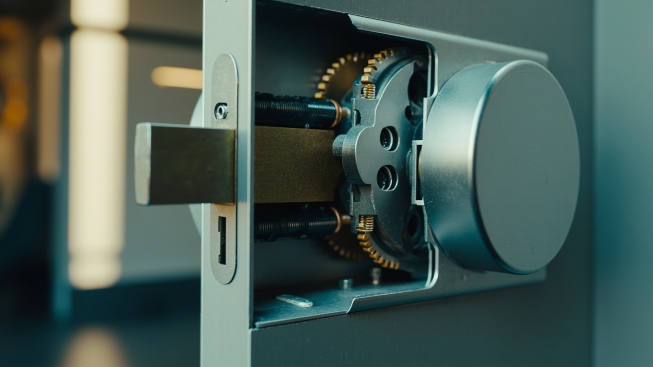
The Mortise Lock Body and Door Compatibility: The Fit Envelope
A qualification meeting can go wrong before a single credential is configured. An integrator places a sample lock body against a door leaf, sees a familiar faceplate, and assumes the hardware will pass through the opening. Then the door arrives with a different backset, the strike recess is too shallow, or the spindle lands below the escutcheon cutout. The lesson is simple: the mortise lock body door fit envelope is not a single dimension, but the complete set of relationships that lets the installed assembly function.
Direct answer. To put it plainly: mortise lock body door fit envelope has to hold for mortise lock body door fit envelope. mortise-lock-body has to hold at the same time. The sections below describe the order mortise lock body door fit envelope is settled in. A mortise lock body door fit envelope describes how one component behaves under load. The datasheet makes claims. mortise lock body door fit envelope is what mortise lock body door fit envelope can be tested against.
mortise lock body door fit envelope is used here in the sense given under mortise lock body door fit envelope. It is a working definition of mortise lock body door fit envelope that carries no regulatory weight. The buyer still has to check it against the dated product page.
The approval that happened before the order
At the sample bench, the useful question is rarely “Does this smart lock perform the required functions?” The earlier question is more physical: will its lock body occupy the actual opening and complete every movement demanded of this door?
That distinction becomes obvious when a project mixes door families. The same escutcheon may appear across an office fit-out, yet one leaf has a narrow stile, another has a deeper frame rebate, and a third carries different existing hardware. An Office Smart Lock Site Survey is therefore more than a photographic record. It is the beginning of the compatibility evidence. Where the opening population is varied, a Smart Lock Retrofit Site Survey can separate the door families instead of treating one successful sample as proof for the entire estate.
Approval at this stage therefore covers the door, frame, lock body and connected hardware as one interface. A smart lock is not an object held in front of a door and made compatible by assumption. It becomes compatible only after the case, spindle, bolt path, strike, panels and operating clearances agree.
A component becomes a system at the door edge
The lock body and mortise case do more than hold a latch. They establish where the mechanical mechanism lives inside the leaf, how rotation reaches the spindle, where the cylinder passes through the door, and how the latch or deadbolt meets the frame. Around that core sit the faceplate, follower, cylinder collar, strike plate, keeper and the escutcheon or panel.
This is why fit must be traced as a chain rather than checked as a collection of unrelated measurements. The case must enter the mortise pocket. The faceplate must sit correctly at the edge. The spindle and cylinder must meet the external hardware. The bolt must travel through the strike opening, and the door must still operate when the closer, hold-open mechanism or other installed hardware is present.
flowchart TD
    A[Identify the door family] --> B[Record leaf and frame geometry]
    B --> C[Compare case and faceplate]
    C --> D[Verify spindle and cylinder datum]
    D --> E[Trace latch and deadbolt]
    E --> F[Check strike and keeper]
    F --> G[Test operation with door hardware]
    G --> H{Fit envelope accepted}
    H -->|Yes| I[Release controlled sample]
    H -->|No| J[Hold and redesign]
The diagram is a qualification path rather than an installation sequence. Its purpose is to prevent the project from jumping from visual similarity to release. Each arrow requires a recorded value, a drawing or an observed test result.
That distinction also keeps commercial discussion in its proper place. The Mortise Lock Body Trade-Offs: Cost, Durability and Service can explain why alternatives are evaluated after their interfaces are understood. Until then, comparing service life or construction without defining the fit envelope risks optimizing the wrong part of the decision.
Start with the door, not the lock family
A door family is a practical grouping of leaves that share relevant geometry and operating conditions. It is not simply a group of doors with the same finish or project code. Before a lock body is compared with the catalogue, the site record must describe the physical door that will receive it.
The primary evidence is the door schedule, supported by field measurements and photographs that show orientation. Where the schedule is incomplete, an integrator needs to know which gaps are design assumptions and which have been confirmed in the field. A visible faceplate is not evidence of a compatible pocket; an apparently standard edge is not evidence of a standard backset.
| Door record | What to capture | Why it changes fit |
|---|---|---|
| Door identity | Project mark, floor, opening and leaf side | Keeps measurements attached to the correct opening |
| Leaf construction | Thickness, edge build-up and visible face material | Determines pocket, faceplate and fastener conditions |
| Handing | Swing direction and handing designation | Identifies the correct case configuration |
| Existing cut-outs | Mortise pocket, spindle bore, cylinder bore and faceplate recess | Shows whether the opening can be reused |
| Frame interface | Strike position, keeper recess and rebate depth | Controls the bolt path and operating clearance |
| Connected hardware | Closer, hold-open device, escape hardware or trim | Affects movement through the full operating cycle |
| Measurement status | Drawing value, field value and responsible verifier | Prevents a drawing assumption from becoming a site fact |
A door schedule should not be silently replaced by a nominal door type. Two leaves can share a schedule reference while differing in thickness, rebate or previous hardware. Conversely, several visibly different doors may belong to one compatible family if the mechanical interfaces agree.
The narrative changes when this record exists. Instead of asking whether an installer can make the lock fit, the team can ask which measured condition rejects it and whether a controlled adaptation is possible.
The mortise case is a coordinate system
A case drawing is useful only when its reference points are visible. The supplier should identify the datum used for the faceplate, the pocket’s permitted boundary, screw locations, spindle position and the relationship to the cylinder or follower. Without those references, two drawings can appear to agree while describing different geometries.
The mortise case dimensions need to include more than overall length and width. Corner form, pocket depth, faceplate projection, screw pattern and the allowance around moving parts can all affect installation. The drawing should show whether dimensions apply to the bare case, an assembled lock or a test fixture, and whether any variation is controlled by a drawing revision.
The first-party catalogue appropriately records lock body/mortise, applicable door thickness, suitable door types, panel dimensions and other door-fit information as separate fields. That separation is commercially important. A model may be associated with a type of door without meaning that every leaf within that broad description has the same pocket or spindle geometry.
One first-party example shows why model-specific evidence matters. The published SLK-9936S hotel lock lists a door thickness of 36–100 mm, a 3-point latch and a 5-pin cylinder. Those values belong to that model and its stated configuration, not to the wider category. Procurement must confirm on the dated product page for the specific SKU before relying on them for a door decision.
When reviewing supplier information, Reading the Mortise Lock Body Claims in a Supplier Datasheet provides a useful discipline: separate a stated capability from the geometry needed to install it. A claim that a case suits a door type is a starting point for comparison, not a substitute for the dimensioned interfaces.
Backset is only meaningful with a declared datum
Backset is one of the most consequential words in a lock drawing, yet it is incomplete unless the drawing states what it measures. The datum may refer to the spindle centreline, the cylinder centreline or another defined reference. A measurement taken from the wrong datum can look precise and still produce the wrong comparison.
A controlled door backset measurement should record the door edge, the reference feature, the tool used and the person responsible for the reading. If the supplier uses a different convention from the installer, the conversion must be explicit rather than assumed. A photograph of a tape measure does not resolve that ambiguity.
Handing belongs in the same geometry record. Door swing direction, case handing and the arrangement of the latch and deadbolt cannot be separated from the spindle orientation. The relevant comparison is the complete handed configuration, not an isolated left or right label that may be interpreted differently between documents.
The door thickness and spindle position then determine how the outer panel or escutcheon meets the inner mechanism. The follower must have room to travel, the spindle must align with the intended bore, and the cylinder or override path must remain clear of the panel and door construction. This is where a surface-level backset comparison stops being enough.
Measure from the physical door rather than from a scaled drawing when the installation decision depends on actual fit. Use the drawing to identify intended geometry and the field to verify the opening. Disagreement between the two becomes a qualification finding, not an argument to be averaged away.
Follow the bolt all the way to the frame
The bolt path is where a visually acceptable case can still fail. The latch or deadbolt emerges through the faceplate aperture and must meet the strike opening at the correct position. The strike plate must sit against the frame face, while the keeper must provide space for the bolt at full travel and under load from the door.
Strike and deadbolt clearance should be checked in the closed, operating and fully extended positions. A static overlap between two plates is not proof that the mechanism can complete its travel. Frame rebate depth, stop projection, door-edge position and the way the leaf closes all influence the space available to the bolt.
The frame therefore belongs in the same fit record as the leaf. Record the strike type, keeper recess, rebate depth and relevant obstruction. Keep the fasteners and fixing points visible in photographs. If the frame cannot accept the intended screw arrangement, the installer may encounter drilling limitations or fixing concerns that a loose-case trial never exposed.
The leaf edge also needs attention. A square-edged sample placed beside a bevelled or stepped door can create a misleading impression. The edge profile affects where the faceplate sits relative to the door face and how the case presents itself to the strike. A compatible faceplate outline is not automatically a compatible edge condition.
This is where the lock body becomes inseparable from the door frame. The case determines the mechanical action; the leaf and frame determine whether that action has room to occur. A qualification that ends at the faceplate has stopped one step too early.
Fit has to survive the door in motion
A door that fits on the bench can still fail during operation. The latch must retract fully while the spindle turns. The deadbolt must extend without binding. The lever or handle must travel through its intended arc, and the case must not pull against the faceplate as the leaf closes under the action of connected hardware.
Closer pressure changes the relationship between the latch, strike and frame. A hold-open device changes the free movement available during entry. Existing trim can alter the spindle path, while a door closer can move the leaf slightly after it appears closed. The sample must therefore be exercised with the relevant hardware present, not tested as an isolated component.
An illustrative qualification often proceeds in three passes. First, the installer closes the door and confirms that the latch and bolt engage. Next, the handle is operated while the door is closed and partially open. Finally, the door is opened, held and released through normal movement. Each pass can reveal a different interface problem.
Where an opening includes an escape device or other safety-related hardware, the mechanical interface must be established for that installed arrangement. The supplier should describe the required latch behaviour and connection points without assuming that every door uses the same configuration. Evidence comes from the door supplier, the installed hardware and a controlled test of the combined assembly.
The Mortise Lock Body Failure Modes Seen on Smart Lock Projects can then be used as a diagnostic reference after fit has been qualified. Here, however, the earlier task is prevention: identify the motion that could cause a failure and include it in the sample test.
The hardware compatibility stack extends beyond the case
The escutcheon, panel and reader sit at the visible end of the assembly, but they do not replace the mechanical interfaces beneath them. A keypad can be correctly positioned over the spindle while the case remains unsuitable for the pocket. A fingerprint sensor and front panel can align with the door face while the cylinder path or follower remains obstructed.
Hardware compatibility should therefore be checked as a stack. The stack may include the panel, lever or handle, keypad, fingerprint sensor, RFID reader, cylinder and rose, motor and gearbox, latch or bolt drive, control board, battery compartment, emergency power port, faceplate, strike plate, keeper, closer, hold-open device and any escape hardware.
Not every product uses every object. A glass door may require a patch fitting rather than a conventional mortise pocket. A cabinet application uses a different lock body and enclosure. A networked product may also introduce a gateway or management layer, while a standalone lock may not. The point is not to assume a common bill of materials; it is to identify which objects actually exist at the opening and which interfaces connect them.
For a system integrator, this prevents a familiar error: validating the electronics while leaving the mechanical route unresolved. The panel may reach the lock body through a spindle, follower or another internal connection, depending on the design. Ask for the actual connection method and operating clearance rather than inferring it from the exterior appearance.
The relationship between the chosen mechanism and long-term operation is explored in How the Mortise Lock Body Drives Smart Lock Reliability. That article addresses performance; the present fit decision comes first because an unsuitable interface prevents a meaningful reliability case from being established.
One sample is not a door schedule
Consider an illustrative retrofit with three opening types. A standard service leaf appears easy because a sample case enters its existing pocket and the bolt reaches the strike. A narrow aluminium leaf has a shallower edge condition, while a glazed screen relies on a patch fitting rather than a conventional mortise installation. The same sample and the same smart-lock platform are presented for all three.
The retrofit lock body fit is therefore not one yes-or-no decision. The sample proves only what it physically demonstrates. It may support qualification of the first door family, trigger further measurement on the second and be irrelevant to the third.
| Illustrative opening | What the sample demonstrates | What must be established next | Likely disposition |
|---|---|---|---|
| Existing leaf with matching pocket | Basic case and faceplate relationship | Backset datum, spindle alignment and full bolt travel | Continue to operational test |
| Leaf with different case geometry | Installed pocket is not automatically reusable | Revised mortise case dimensions and opening condition | Hold pending redesign |
| Leaf with a glazed section | Conventional mortise route may not apply | Patch-fitting and hardware arrangement for that opening | Evaluate a different installation approach |
| Frame with altered strike condition | Leaf-side fit alone is insufficient | Keeper, rebate and bolt clearance under operation | Verify frame interface or revise |
The lesson is not that unusual doors are unsuitable for smart locks. It is that unusual conditions require a different evidence path. A sample proves fit at the condition in which it was tested; it does not transfer that proof to an unmeasured door.
That is why a controlled sample should be labelled with the door family it represents. The label should point back to the geometry record and identify which conditions were changed during the trial. Without that traceability, a successful photograph can be reused far beyond its evidential scope.
The fit decision changes with the consequence of mismatch
Not every mismatch deserves the same response. If the case does not enter the pocket, adaptation may be possible. If the bolt cannot reach the keeper or the door cannot complete its movement, accepting the mismatch risks an unreliable installation. The decision path should reflect both the physical remedy and the operational consequence.
| Decision path | Use when | Main benefit | Evidence required before release | Residual concern |
|---|---|---|---|---|
| Accept the opening as recorded | Case, spindle, bolt path and connected hardware match the verified door condition | Preserves the existing door and avoids unnecessary work | Dimensioned record plus controlled installed test | Future door revisions may alter the basis |
| Replace or fabricate the leaf | The pocket, faceplate, spindle or bolt geometry cannot meet the intended arrangement | Lets the lock interface be designed as one controlled assembly | Approved door drawing and supplier geometry | Fabrication changes must remain synchronized |
| Evaluate an alternative case | A different lock-body geometry can satisfy the measured interface without changing the opening | Preserves more of the existing door construction | Side-by-side interface comparison and sample trial | Different operating and maintenance characteristics |
| Reject or redesign the opening | No feasible arrangement provides safe movement or required access | Avoids forcing an unsuitable installation into service | Documented decision and revised design requirement | The project needs an alternative access solution |
A comparison table should record why one path was selected, not only which path was selected. If the existing opening is accepted, the evidence file should identify the door revision that was checked. If the leaf changes, the original lock-body drawing is no longer enough; the new door drawing becomes part of the same fit record.
This decision discipline also prevents late substitutions. A different strike, closer or panel may look locally harmless but alter the envelope that was previously accepted. The decision table therefore works only if every changed component is routed back through the qualification sequence.
Evidence should progress from claim to controlled geometry
The strongest fit evidence is connected, specific and revision-controlled. A product photograph can identify the general form, but it cannot prove the pocket dimensions, spindle relationship or bolt travel. A catalogue statement can narrow the candidate set, but it cannot replace a dimensioned drawing for the proposed opening.
For the supplier, the request should ask whether it can provide dimension drawings, an installation guide and a datasheet on request for the exact lock body and configuration. Any model-level dimension that drives procurement must be confirmed on the dated product page for the specific SKU. A drawing supplied for one revision should not silently be carried into another.
At the integrator side, the evidence chain should move through a field record, a marked-up door geometry, a supplier comparison, a controlled sample and an installed mock-up. Each stage should preserve the same identifiers: opening, door revision, lock-body configuration and hardware set. Photographs should include scale references and views from both the door edge and frame interface.
The supplied document should also explain what the dimensions mean. Labels such as “backset”, “case width” or “bolt size” are not self-defining. Ask for the datum, measurement method and whether tolerances apply. Where the supplier leaves an item unresolved, record it as unresolved rather than filling the field with a value borrowed from another model.
Traceability matters because installation evidence tends to be fragmented. The person who measured the door may not be the person who compares the drawing, and the sample may arrive after the original survey. A single controlled record prevents those handoffs from becoming disagreements.
Turning the mortise lock body door fit envelope into a qualification
A scorecard gives the qualification team a shared definition of “fit”. It should not reduce the decision to a visual pass. Each gate has to name the evidence that closes it and the condition that returns the opening to design or survey.
| Qualification gate | Evidence that closes the gate | Fail signal | Status |
|---|---|---|---|
| Identity and datum | Named case configuration, drawing revision and stated reference points | Supplier and installer use different datums | Open |
| Case and faceplate | Measured pocket compared with the permitted case boundary and faceplate arrangement | Case interferes or cannot be seated as documented | Open |
| Spindle and cylinder | Field centres compared with the intended panel, follower and cylinder route | Rotation or override path is obstructed | Open |
| Latch and deadbolt | Faceplate opening, strike, keeper and full travel checked together | Bolt binds, misses or cannot project correctly | Open |
| Connected hardware | Door exercised with closer, hold-open, trim or escape hardware present | Installed hardware changes the required movement | Open |
| Operating record | Repeated close, lock, unlock and release cycle recorded on the controlled sample | Function depends on forcing or holding the door | Open |
Use simple statuses such as accepted, hold and rejected. “Accepted” means the evidence closes that gate for the recorded configuration; it is not a promise that every future door in the project shares the same geometry. “Hold” identifies missing evidence without pretending the design has failed. “Rejected” should point to the specific interface that cannot be accepted.
The scorecard is valuable because it separates a fit issue from a documentation issue. A missing dimension may prevent a decision even when the physical relationship appears likely. Conversely, a dimension that has been verified can move the opening forward without delaying unrelated work.
Build the RFQ packet as a set of answers
The request for quotation should make the supplier answer the same mechanical questions the integrator will later test. Sending a model name and a general door description is not enough. The packet should carry a controlled door geometry schedule and a question set tied to the proposed lock body.
A useful request contains the following items:
Proposed case identity: Name the exact lock body or model configuration, drawing revision, handing, faceplate and applicable finish. Do not allow the case to be substituted without renewed qualification.
Door geometry schedule: Include leaf thickness, edge construction, handing, existing pocket references, spindle and cylinder positions, faceplate condition, frame rebate, strike position and keeper details for every door family.
Interface schedule: Request the mortise case dimensions, pocket boundary, faceplate geometry, screw pattern, spindle and follower arrangement, cylinder path, latch and deadbolt details, and the intended strike and keeper arrangement.
Datum statement: Ask the supplier to identify how backset and other centre distances are measured. Request tolerances or permitted adjustments exactly as stated in the controlled document.
Connected-hardware schedule: Identify the panel, handle or lever, cylinder, closer, hold-open device, escape hardware and any other component that interacts with the case or bolt.
Operating conditions: Describe how the door should close, latch, lock, unlock and release, including the positions in which the latch must retract and the spindle must travel.
Evidence package: Request dimension drawings, the installation guide and a datasheet on request, together with any available sample or test information for the exact configuration.
Change-control request: Ask the supplier to identify how drawing revisions, case substitutions and hardware changes will be communicated before they affect an approved sample.
Attach the marked-up door record to the request. Then ask for a controlled sample against the door family represented by that record, rather than accepting a general display unit as proof of fit. Once the geometry and evidence are settled, the same package can enter the request-a-quote workflow without leaving the mechanical questions behind.
A repeatable qualification sequence for the integrator
The sequence matters because each role sees a different portion of the problem. The surveyor sees the actual opening. The supplier sees the case and its controlled dimensions. The installer sees the panel, fasteners and operating hardware. The buyer sees the configuration that will be repeated. A qualification process that assigns all of this to one person at the final inspection is vulnerable to a missed handoff.
- Identify each distinct door family and link it to a measured record.
- Obtain the proposed case geometry, datums and model-specific documentation.
- Compare the case, spindle, cylinder and panel interfaces.
- Trace the latch or deadbolt into the actual strike and keeper.
- Fit the controlled sample with the connected door hardware present.
- Record operating results and close or hold each qualification gate.
- Release the configuration only against the accepted door and drawing revisions.
The record should follow the project rather than the meeting. When a frame is replaced, the panel is changed or a new closer is introduced, the relevant gates return to hold. The purpose is not paperwork for its own sake; it is to make the next physical change visible before it becomes a field surprise.
The approval that matters is reversible
At the end of the qualification, the smart lock has earned more than a place in the equipment schedule. It has earned a defined place in a particular door. The case has a named geometry. The spindle and cylinder have a declared relationship to the panel. The bolt has reached a verified strike. The installed hardware has been included in the movement test, and every assumption still open is visible.
That approval should be reversible because buildings change. A revised door schedule, substituted closer, revised strike or alternate escutcheon can change one interface without changing the rest of the project description. When that occurs, the qualification record shows exactly what needs to be checked again.
The final decision therefore belongs to the door family, not to the display sample. For each accepted family, send the controlled geometry, selected evidence and sample results through the order samples or quotation workflow. Keep the same revision attached to the request, and do not let a convenient lock body become the reason to alter a door that has already been assessed.
The same question is worked through in more detail in what smart lock is best for wooden doors. That is the same question mortise lock body door fit envelope has to answer here.A well-qualified mortise lock body is almost invisible when it works. The handle turns, the latch retracts, the bolt settles into the strike and the door closes without intervention. The discipline behind that ordinary movement is a fit envelope built from measurements, drawings, tests and an honest record of what remains unverified.