
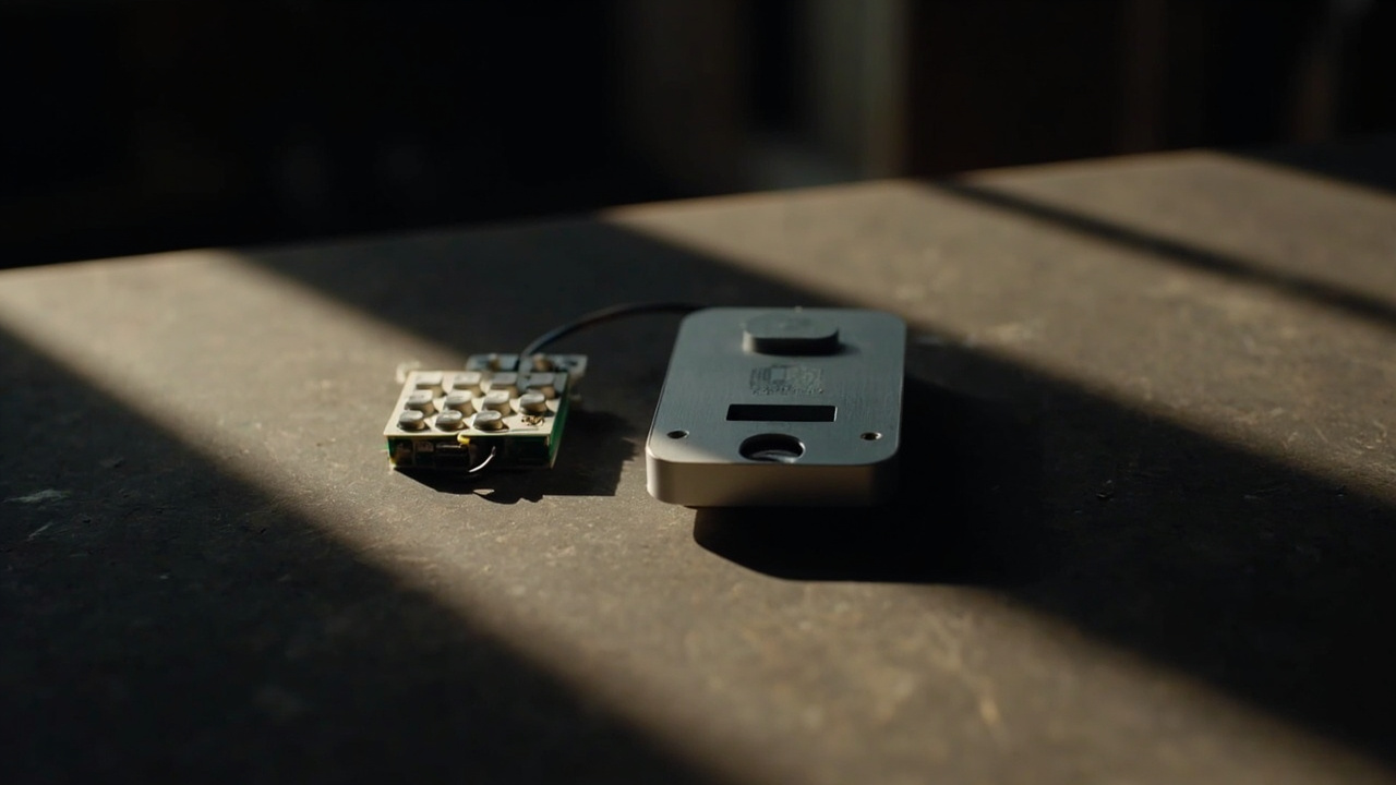
Capacitive and Mechanical Keypads Failure Modes Seen on Smart Lock Projects
System integrators need to separate a keypad complaint from a power, credential, lock-body or door-fit problem. This component teardown maps capacitive and mechanical keypad failure modes to observable symptoms, likely fault layers, and evidence worth recording before a replacement decision. It is written for qualification: decide what to test, what to document, and when the evidence is strong enough to close the issue.
Direct answer. The one-line answer — capacitive and mechanical keypad failure modes is the working record for capacitive and mechanical keypad failure modes. capacitive and mechanical keypad failure modes is worthless until capacitive-and-mechanical-keypad is attached to it as evidence. A capacitive and mechanical keypad failure modes is a component behaviour guide. It covers limits. It covers failure modes. capacitive and mechanical keypad failure modes decides whether capacitive and mechanical keypad failure modes is acceptable for this build.
capacitive and mechanical keypad failure modes is used here in the narrow sense set out in capacitive and mechanical keypad failure modes. It is a working definition built for capacitive and mechanical keypad failure modes. It is not a statutory one, and it has to be read against the market and product concerned.
Separate the keypad from the rest of the lock
Trace the operating chain in this order: user input, keypad controller or contact matrix, control PCB, motor and gearbox, latch or bolt, strike, and door. A code can be entered without reaching the credential logic; a credential can be accepted while the motor fails to drive the latch. Those are different faults.
Mechanical override access, when the selected product includes it, provides another diagnostic route. Its condition helps separate an electronic input problem from a complete lock outage, but it does not clear the keypad. Pair this teardown with an Office Smart Lock Site Survey rather than using keypad symptoms as a substitute for door measurements.
Capacitive layer: surface symptom to sensing evidence
Capacitive keypad failure diagnosis starts by determining whether the controller receives unintended, missing or distorted key events. The visible face, sensing element, connection and input processing may be separate service boundaries. A supplier must identify the architecture; a glass-front panel alone is not evidence of capacitive sensing.
| Symptom | Fault layer to test | Controlled check | Evidence to retain |
|---|---|---|---|
| Unintended digits, or keypad ghost presses | Surface contamination, moisture, grounding path or input processing | Reproduce a fixed key sequence under controlled, dry conditions | Photos, exact sequence and unlock records if available |
| One key or zone is dead | Sensing element, trace, connector or controller channel | Map affected keys and inspect the connection using the supplier procedure | Key map, video and service record |
| Sensitivity changes after cleaning or damp exposure | Surface condition, keypad water ingress or unstable sensing reference | Change one condition at a time, then repeat the same sequence | Before-and-after result and environmental note |
| The lock wakes but rejects the code | Credential or unlock logic may be downstream of correct key input | Separate key recognition from credential acceptance | Event log, programming record and override result |
| No display or wake indication | Power path, connector or controller | Check documented supply state and any specified emergency-power arrangement | Supply-state photo and fault log |
Capture the event sequence before cleaning or resetting. Drying a surface may remove the symptom without identifying whether contamination, keypad water ingress or a grounding path caused it.
Mechanical layer: contact path and assembly consistency
Mechanical keypad failure diagnosis follows a different path. It starts with the physical closure of each key contact, then checks alignment, debris, wear and the connection between the contact matrix and controller. Mechanical construction does not eliminate the electronic verification stage: a correctly closed contact must still be recognized and accepted.
| Symptom | Fault layer to test | Controlled check | Evidence to retain |
|---|---|---|---|
| No tactile click and no registered key | Plunger, dome, metal contact or contact matrix | Press each key using the same technique and compare the response | Key map, video and removed-component photographs |
| Click feels inconsistent or code entry is intermittent | Debris, contact wear, oxidation or alignment | Inspect the contact area and repeat a fixed entry sequence | Inspection notes, contact images and sequence result |
| One character repeats or chatters | Contact bounce, debris, over-travel or alignment | Test the affected key separately from the surrounding keys | Repetition count, key location and service history |
| Several keys stop after panel service | Reassembly alignment, connector seating or pinched wiring | Inspect the panel and connector before replacing the controller | Before-and-after photographs and assembly record |
| Entire keypad becomes inactive | Shared connector, controller or power branch | Compare with other access methods and check the documented supply state | Fault log, configuration record and override result |
Do not assume that a visible click proves successful code entry. The decisive distinction is whether the controller records the intended key event.
Where capacitive and mechanical evidence converges
For capacitive and mechanical keypad failure modes, the most useful evidence preserves the same chain: symptom, component boundary, controlled test, result and disposition. The architecture changes what is inspected, but not the need to separate input recognition from credential acceptance.
| Decision point | Capacitive evidence | Mechanical evidence | Procurement action |
|---|---|---|---|
| Contamination or wear | Surface condition and repeatability after cleaning | Key travel, debris and contact consistency | Request a controlled comparison before replacing the module |
| Input recognition | Key-event mapping and controller behavior | Contact mapping and tactile response | Obtain logs or test evidence that identifies the input stage |
| Service boundary | Sensing element, connection and controller | Plunger, contact, connection and controller | Require the supplier to state module boundaries and test access |
| Strongest close-out record | Before-and-after sequence under stated conditions | Contact inspection plus before-and-after entry sequence | Require the same evidence standard for both architectures |
The Capacitive and Mechanical Keypads Trade-Offs: Cost, Durability and Service provides a useful comparison frame, but the trade-off discussion does not replace fault-boundary evidence.
Controlled isolation sequence
Record the configuration and symptom before resetting the lock. Then isolate the chain in a fixed order so that one test does not erase the conditions needed to reproduce the next symptom.
flowchart TD
    A[Capture exact symptom and configuration] --> B[Confirm power and other access paths]
    B --> C[Map every key in a controlled sequence]
    C --> D[Inspect surface alignment and connection]
    D --> E[Compare key events with unlock decision]
    E --> F[Record evidence and disposition]
Use supplier-specified test points and procedures rather than improvised probing. During keypad wear inspection, record key travel, return consistency, visible damage and connector condition without assuming that appearance identifies the failed part.
If no key event appears in the records, focus on the panel-to-controller boundary. If the event appears but the credential is rejected, continue into the credential and unlock decision chain.
Build an evidence packet that a supplier can act
An evidence sheet should identify the observed symptom, affected component boundary, test method, result, configuration and corrective action. A photograph without context or a statement that the keypad was replaced is not a root-cause record.
Request the following for the exact production configuration:
- Architecture statement: the sensing method, model version, service boundaries and definition of a recognized key event.
- Reproduction protocol: the starting condition, key sequence, environmental condition and points at which the lock was reset.
- Boundary evidence: key maps, photographs or video, event records and documented supply-state checks.
- Configuration trace: panel, controller, power arrangement, credential programming, door fit and recent service history.
- Corrective-action evidence: the containment step, technical change, validation method and scope of affected versions.
The Capacitive and Mechanical Keypads Test Evidence a Buyer Can Actually Request expands this request into a test-evidence checklist. For claim review, use the Reading Capacitive and Mechanical Keypads Claims in a Supplier Datasheet to separate a stated feature from evidence that the feature was tested.
The practical counterpart to this point is the smart lock communication architecture. That is the same question capacitive and mechanical keypad failure modes has to answer here.
Three illustrative project patterns
The following are diagnostic patterns, not customer case histories.
- Keypad ghost presses cluster around cleaning or damp conditions: isolate the affected area, reproduce a fixed sequence under controlled conditions and document whether the behaviour persists.
- A key becomes intermittent after panel service: inspect contact alignment, debris, connector seating and cable routing before attributing the fault to the controller.
- The keypad is inactive while another electronic credential still works: investigate the panel, input branch and its power path rather than assuming the motor or credential service has failed.
For retrofit work, connect these observations to the Smart Lock Retrofit Site Survey. A keypad that behaved correctly before a door modification may now sit outside the tested mechanical or electrical conditions.
Convert the fault history into a keypad acceptance test
Use a keypad acceptance test that measures behavior under recorded conditions. Agree the protocol with the supplier before installation, and make the pass condition part of the handover record.
- Freeze the configuration: exact model and version, panel, controller, power arrangement, credential set and door condition.
- Map every key. Record the intended event, duplicate events and any adjacent key that responds incorrectly.
- Run a supplier-defined sequence for valid and invalid credential handling without changing any other variable.
- Repeat the sequence during normal use and after the documented service state, using supplier-defined repetition criteria.
- Evaluate surface or environmental sensitivity only under the written test procedure; do not apply unapproved liquids or contaminants.
- For a mechanical keypad, inspect travel, return and alignment. For a capacitive keypad, inspect the sensing surface, visible damage and connection condition.
- Correlate key events with unlock records and confirm that the documented emergency or override route remains usable where applicable.
Retain the results, photographs and configuration record as project evidence. Do not reduce the handover to a visual statement that the keypad appears operational.
Read first-party catalogue records carefully
The first-party catalogue contains 18 models in the Keypad category, while 55 of its 79 models record passcode/keypad capability. These counts describe catalogue composition; they do not establish whether a particular panel uses capacitive or mechanical input.
The catalogue records the SLK-1103 with passcode/keypad and RFID/IC card access, a high-purity zinc-alloy die-cast body, a deadbolt mortise, four AA batteries and an external power override through a USB terminal. Confirm on the dated product page for the specific SKU before using any of those fields in an approved project requirement.
The SLK-019 is recorded in 304 stainless steel, with passcode offered by model version. The supplied catalogue rows do not identify the keypad sensing architecture, so request it separately rather than inferring it from the finish or construction.
Turn the teardown into a qualification disposition
Use the evidence to assign the issue to the narrowest responsible boundary:
- Installation or handling correction: the fault is isolated to assembly, alignment, connector condition or another installation-controlled factor.
- Module or supplier corrective action: repeated testing maps the failure to the keypad component, controller interface or a defined model version.
- Whole-lock escalation: evidence shows that the keypad is only one visible symptom within a broader power, controller, motor, latch or door-chain failure.
CONFIRM-WITH-LOCAL-ACCESS-CONTROL-INTEGRATOR: Verify project-specific environmental, access-control and acceptance requirements against the approved lock configuration and the applicable local project requirements.
Use this teardown as the qualification request attached to the exact SKU. That gives the manufacturer a configuration-specific basis for diagnosis rather than a generic keypad promise.
A settled specification becomes a comparable offer through request a quote.