
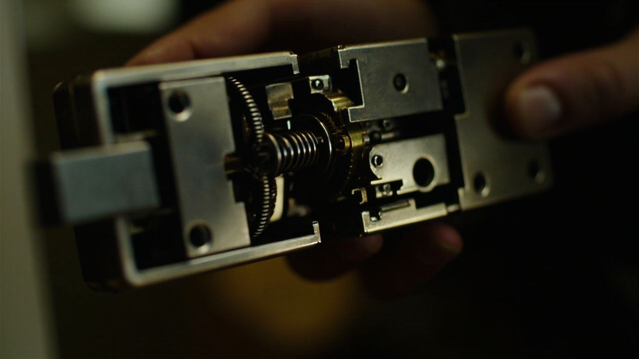
The Intelligent Cylinder Failure Modes Seen on Smart Lock Projects
Qualification often begins after a pilot door behaves ambiguously: the handle turns, a credential is accepted, or an event appears in the system, yet the bolt does not reach a stable position. That observation is not a diagnosis. The intelligent cylinder failure modes that matter to a system integrator are those that can be isolated across the cylinder, spindle, lock body, latch or deadbolt, strike, door leaf and frame.
Direct answer. The one-line answer — intelligent cylinder failure modes is the working record for intelligent cylinder failure modes. intelligent cylinder failure modes is worthless until intelligent-cylinder is attached to it as evidence. An intelligent cylinder failure modes is a component behaviour guide. It covers limits. It covers failure modes. intelligent cylinder failure modes decides whether intelligent cylinder failure modes is acceptable for this build.
intelligent cylinder failure modes means here what intelligent cylinder failure modes sets out. It is a working definition of intelligent cylinder failure modes for this market and product. It is drawn from the evidence below, and it is not a general marketing phrase.
This handbook treats each mode as a clause with a trigger, verification method, evidence record and disposition rule. The modes are diagnostic categories, not allegations against a named product. They provide a disciplined starting point for smart lock cylinder troubleshooting and electromechanical lock troubleshooting before a defect is assigned to the wrong component.
The first task is to document what the project means by “cylinder failure.” The supplier and integrator should identify the assembly boundary, the operating sequence and the evidence expected for each symptom. That prevents a mechanical binding issue, a frame-load issue and a control-log issue from being collapsed into one unresolved ticket.
flowchart TD
    A[Define cylinder boundary] --> B[Register observable symptom]
    B --> C[Reproduce under controlled conditions]
    C --> D[Record physical and system evidence]
    D --> E[Assign responsible boundary]
    E -->|Boundary unresolved| F[Hold as system fault]
    F --> C
    E -->|Boundary isolated| G[Apply defined correction]
    G --> H[Retest under equivalent conditions]
    H --> I[Evidence satisfies clause]
    I -->|No| C
    I -->|Yes| J[Close and freeze configuration]
Qualification scope and the cylinder boundary
The cylinder may be a mechanical credential core, an electromechanical module integrated into the lock, or a separately specified component within a larger lock architecture. The project should not rely on the product category to determine that boundary. Ask for a drawing and bill-of-materials entry showing which parts move together and which failures belong to another subsystem.
| Boundary item | What the buyer must define | Qualification evidence |
|---|---|---|
| Cylinder assembly | Rotation, locking and emergency-access functions assigned to it | Annotated drawing and interface description |
| Spindle or follower | How input motion reaches the lock body | Coupling method, retention and inspection points |
| Mortise case and lock body | Which bolt operations are controlled outside the cylinder | Functional boundary and fault indicators |
| Latch and deadbolt | Required travel, retraction and return sequence | State sequence and acceptance observations |
| Strike and frame | Fixed receiving hardware excluded from cylinder diagnosis | Site measurements and door operating condition |
| Door and closer | External loads applied during testing | Door fit verification record |
| Control and power | Electronic functions that may influence cylinder behavior | Recovery sequence and event-recording scope |
| Override access | Which mechanical function remains available during an electrical fault | Project-specific operating instruction |
Smart Lock Factory’s product facts identify the cylinder and cylinder collar or rose among 35 hardware objects that a buyer can inspect, specify or reject. They also list the spindle, mortise case, latch, deadbolt, strike keeper, door frame rebate, door leaf and backset as separate objects. That object-level distinction should appear in the qualification documents rather than being hidden inside a broad “smart lock” description.
The supplied catalogue records a mechanical override key for 63 of the 79 published models. This is catalogue composition rather than a guarantee for a proposed SKU. Confirm on the dated product page for the specific SKU before assigning emergency access to its cylinder architecture. For shared terminology, use the Smart Lock Glossary: Intelligent Cylinder Definition for B2B Buyers, then review The Intelligent Cylinder Trade-Offs: Cost, Durability and Service without treating a general trade-off as evidence that a particular design will perform in the project.
Failure register: symptom to evidence
A useful failure-mode register separates an observation from a cause. It also prevents a supplier response such as “adjust the door” from becoming a closure statement before the actual interface has been examined.
| ID | Failure mode | Observable symptom | Boundary most likely involved | Minimum record |
|---|---|---|---|---|
| FM-01 | Binding under actuation | Rotation stops or becomes inconsistent | Cylinder, spindle or lock body | Position, door condition and reproduction sequence |
| FM-02 | Override mismatch | Key moves but does not complete the intended action | Cylinder or override interface | Key, insertion and rotation observations |
| FM-03 | Coupling slip | Handle moves without corresponding bolt travel | Spindle or follower | Coupling condition and movement correlation |
| FM-04 | Incomplete throw | Latch or deadbolt stops before stable engagement | Lock body, bolt or strike | Travel state and load condition |
| FM-05 | Irregular return | Bolt retracts or fails to reset consistently | Motor, gearbox or return path | Ordered state sequence |
| FM-06 | Power-state ambiguity | Operation changes after interruption or restart | Power, control or cylinder electronics | Recovery state and event record |
| FM-07 | Contamination or corrosion | Increased resistance or erratic sensing | Cylinder interface or environment | Visual condition and maintenance history |
| FM-08 | Frame-induced load | Fault appears only when the door is closed | Frame, closer, strike or bolt | Door geometry and load observations |
| FM-09 | Wear drift | Performance changes over repeated use | Cylinder, coupling or actuator | Baseline and repeated-use comparison |
| FM-10 | Misattributed symptom | System reports failure while another part is responsible | Reader, control, lock body or credential | Isolation result and remaining evidence |
Each ticket should cite one or more register IDs, but it should not close on the ID alone. The record must connect the symptom, reproduction steps and component boundary to a disposition. If those links are missing, the fault remains a symptom report rather than a resolved engineering issue.
Clause 01 — Binding under repeated actuation
Trigger. Resistance appears during key rotation, credential-driven actuation or spindle movement. The operator may describe the lock as jammed even though the motor, reader and event system appear normal.
Verification. Reproduce the action under controlled conditions with the door in the states that matter to normal operation. Record whether resistance occurs before cylinder rotation, during transfer to the spindle, or only after the bolt meets a load. Compare the result with the operating envelope stated for the proposed SKU; do not invent a force or torque limit.
Evidence. Capture the starting door position, attempted action, observed motion, sound or hesitation, and whether another authorized method completes the operation. Photograph the visible interface without disassembling an energized product outside the supplier’s instructions.
Disposition. Hold the fault for engineering analysis when binding repeats under repeatable conditions and no component cause has been assigned. A general instruction to lubricate, adjust or replace the lock is not closure evidence. The response must identify the corrected interface, the retest sequence and the configuration used.
Clause 02 — Override mismatch and incomplete emergency action
Trigger. A mechanical key enters the cylinder but the expected latch, deadbolt or emergency operation does not follow. The fault may be in the keyway, cylinder, follower, spindle, lock body or door assembly.
Verification. Follow the project’s authorized override sequence and separately record key insertion, key rotation, thumb-turn or cam position, spindle movement and bolt response. Mechanical override alignment must be checked as a chain, not inferred from key movement alone.
Evidence. Note the key profile used, the cylinder and override configuration, the door position, the observed bolt state and whether the door can be operated safely afterward. If multiple override methods are proposed, identify which steps are identical and which are specific to the selected SKU.
Disposition. Reject closure based only on “the key turns.” Closure requires evidence that the defined override function reaches its intended end state or that the project has formally changed that requirement. As one hotel-specific example, the supplied SLK-9936S fact block records a 5-pin cylinder, a 3-point latch and mechanical emergency access.
Clause 03 — Loss of motion at the spindle or follower
Trigger. The user action is visible but is not transferred to the bolt, or the bolt moves while the expected cylinder indication does not change. This pattern is often logged as an electronic failure because the command was accepted.
Verification. Inspect the interface according to the supplier’s instructions. Check for a loose, worn, displaced or incorrectly assembled coupling. Confirm whether the design transfers rotation directly, through a follower or through another mechanical arrangement. The interface must be compared with the selected drawing, not a generic cylinder illustration.
Evidence. Record the motion observed at the user interface, at the spindle or follower, and at the lock body. Include configuration references, visible condition and the method used to separate the interfaces. Do not substitute an electrical event log for the missing mechanical observation.
Disposition. If motion is lost at the interface, assign the fault to the coupling boundary and require a corrected assembly, replacement instruction or approved alternative.
Clause 04 — Incomplete bolt travel or inconsistent return
Trigger. The latch or deadbolt does not reach a stable thrown state, retracts too far, remains partly extended or returns intermittently. The operator may report that the door “did not lock,” even though the cylinder rotated normally.
Verification. Separate bolt behavior from cylinder behavior. Record the action with the door unloaded and with the door in its normal closed position. Observe the full sequence from input to throw, stable position, reset request and return. Any test limit must come from the dated product documentation or an engineering response for the specific configuration.
Evidence. Use a state record rather than a yes-or-no result. Capture command acceptance, attempted travel, visible bolt position, door condition and the point at which the sequence stopped.
Disposition. Keep the fault open when the cylinder moves correctly but the bolt does not complete its declared path. Require the supplier to determine whether the cause lies in the cylinder interface, lock body, bolt, strike, frame load or control sequence. Do not close the item by increasing force at the door.
Clause 05 — Power interruption during an actuation sequence
Trigger. A lock changes state after power is interrupted, restored or deliberately placed into a service condition. Symptoms may include a bolt left between positions, an event that does not match the physical state, or repeated commands that do not produce the expected movement.
Verification. Test the recovery sequence defined for the selected architecture. Establish which state is intended before interruption, immediately after restoration and after the first authorized command.
Evidence. Record the interruption point, visible mechanical state, restored state, control indication, event entries and the number of commands needed to recover. Preserve the original configuration; do not change several variables during the same test.
Disposition. An event log showing “failure” is not enough. The supplier must correlate the electrical state with the physical position and state what behavior is permitted. Any behavior not supported by the dated product page or engineering response remains an unresolved qualification item.
Clause 06 — Contamination, moisture and abrasive wear
Trigger. Resistance becomes intermittent, the bolt slows near a consistent position, or performance changes after cleaning, weather exposure or construction debris enters the door interface.
Verification. Inspect accessible surfaces, seals, the cylinder interface and the lock case for debris, abrasion, moisture or corrosion. Use only approved cleaning methods. Establish whether the symptom occurs with the door open, closed or both, because a closing load can magnify a small interface problem.
Evidence. Record the environment, visible condition, cleaning performed, location of the symptom and behavior immediately before and after cleaning. Include photographs where the installer is authorized to take them and preserve the configuration reference.
Disposition. Do not convert a general weather-resistance statement into a project guarantee. Ask what condition changed, whether the supplier attributes it to contamination or damage, and what corrective or preventive action is required. The clause closes only with a defined correction and repeat observation under the same conditions.
Clause 07 — Frame load presented as a cylinder fault
Trigger. The fault appears only after the door closes, the closer takes up, a hold-open device releases or the latch is loaded against the strike. Another door in the same building may behave differently with the same lock configuration.
Verification. Complete door fit verification before assigning the symptom to the cylinder. Record door leaf, frame rebate, backset, strike keeper, latch engagement and any closer or hold-open equipment. Compare the symptom with the door in controlled open and closed positions without treating either state as automatically correct.
Evidence. Use the Office Smart Lock Site Survey to capture site inputs and the Smart Lock Retrofit Site Survey where existing doors or frames are involved. Keep photographs, measurements and the symptom sequence in one project record.
Disposition. When the symptom disappears after removing external load, assign it to the interface requiring correction rather than replacing the cylinder by assumption. Closure requires evidence that the corrected door or lock configuration completes the defined sequence.
Clause 08 — Wear drift without an obvious broken component
Trigger. Early in the project, the same action produces progressively longer response, more hesitation or a different final position. There may be no visible fracture, and a simple pass-or-fail inspection may miss the change.
Verification. Establish a repeatable baseline using the proposed door, hardware and operating sequence. Compare early observations with later ones, retaining the number of completed cycles, environmental conditions and any maintenance events.
Evidence. Record the baseline, repetition method, trend, affected interface and whether the change is gradual, sudden or condition-dependent. The The Intelligent Cylinder Test Evidence a Buyer Can Actually Request provides the adjacent evidence questions for this disposition.
Disposition. A visual pass does not close a drift complaint. Require a cause, a corrective action or an explicit finding that the observation lies outside the declared operating envelope. The project must also state who will monitor the condition after deployment.
Clause 09 — The symptom belongs to another lock subsystem
Trigger. A cylinder ticket grows because every failed unlock is sent to the same engineer. The actual issue may sit in the reader, credential layer, control module, event store, lock body or another part of the door assembly.
Verification. Use lock body diagnostics as a fault-isolation method, not as a final cause. Compare the physical bolt position with the control indication, credential acceptance and stored event. Under controlled conditions, determine whether the request reaches the cylinder and whether the cylinder can move independently of the reported electronic event.
Evidence. Record every stage between user input and physical movement, including configuration, event timestamps, physical observations and the isolation step used. The The Intelligent Cylinder in a Smart Lock: What a Buyer Should Understand clarifies which parts should be evaluated together.
Disposition. Transfer the fault only when the evidence assigns it to another boundary. If the stages cannot be separated, the ticket remains a system fault. Do not order a cylinder replacement merely because the event log lacks a physical confirmation.
Evidence escalation ladder for unresolved faults
Qualification test evidence should answer three questions in order: what was observed, where was the boundary, and what changed after the proposed correction. A stronger marketing statement cannot replace any of them.
| Evidence level | Evidence offered | What it can establish | Limitation to record |
|---|---|---|---|
| 1 | Direct physical inspection | Visible condition at a named interface | May not reveal intermittent internal behavior |
| 2 | Controlled reproduction | Repeatability under stated conditions | Results depend on the defined sequence and setup |
| 3 | State and event correlation | Relationship between command and recorded state | An event may not prove physical movement |
| 4 | Before-and-after comparison | Effect of a correction | Both sets must use equivalent conditions |
| 5 | Supplier verbal statement | Intended design rationale | Does not replace an observable result |
Each escalation level should retain the lower-level records. A photograph without a location reference, a log without a physical state, or a test without configuration details leaves a gap. The buyer should ask the supplier to identify which evidence is direct, which is inferred and which remains outstanding.
Supplier response comparison: weak answer versus testable answer
The response comparison should happen before samples are approved. It is more useful than comparing broad claims because each answer can be traced to a failure mode and an evidence request.
| Failure mode | Weak supplier response | Testable supplier response | Buyer decision |
|---|---|---|---|
| Binding | The lock operates normally | Supplies the operating envelope and a controlled reproduction method | Hold until the limit is tied to the SKU |
| Override mismatch | The emergency key works | Defines the complete override sequence and expected end state | Accept only the demonstrated sequence |
| Coupling slip | Torque should be sufficient | Identifies the coupling design, retention method and inspection point | Hold until the interface is documented |
| Incomplete throw | Adjust the strike | Separates bolt travel from frame load and requests a corrected configuration | Reject a closure with no fault boundary |
| Power interruption | The controller will retry | Defines the state before, during and after restoration | Hold until physical state is correlated |
| Contamination | Use a sealed product | Defines the accessible interface, approved cleaning and response to residue | Reject a generic environmental claim |
| Frame-induced load | The door needs adjustment | Provides a site diagnosis sequence and post-correction evidence | Assign the fault to the site interface |
| Wear drift | It meets the rated cycle count | Provides relevant qualification evidence and a monitoring or replacement rule | Require project-specific acceptance criteria |
Score each response before comparing commercial or technical proposals. A response marked “partial” remains partial even if the rest of the submission is detailed. The buyer should set the minimum acceptable evidence level before issuing the request and require the supplier to identify any clause it cannot support.
RFQ clause set for intelligent cylinder qualification
The following clauses can form the technical portion of a request for quotation or qualification pack. Project-specific values must come from the dated product page or the supplier’s engineering response.
- Q-01 — Architecture boundary. State which functions belong to the cylinder, spindle or follower, lock body, latch or deadbolt, strike, door assembly, control and power subsystem.
- Q-02 — Failure-mode response. For each proposed intelligent cylinder failure mode in the supplier’s response, identify the observable symptom, likely boundary and corrective ownership.
- Q-03 — SKU confirmation.
- Q-04 — Cylinder acceptance testing. Define cylinder acceptance testing for the proposed sample, including door condition, operating sequence, power condition, repetition method and the evidence retained.
- Q-05 — State recovery. Describe the mechanical and recorded states before, during and after an interrupted actuation, without relying on an unqualified restart statement.
- Q-06 — Door interface. Provide the expected interface with the door leaf, frame rebate, backset, strike keeper, latch or deadbolt, closer and hold-open equipment.
- Q-07 — Sample identity. Ensure every sample and test unit has a traceable SKU, configuration, software or control revision where applicable, and supplied accessory identity.
- Q-08 — Deviation control. Identify every proposed sample feature, component substitution or configuration change that differs from the dated product page for the specific SKU.
- Q-09 — Commissioning transfer. Supply the approved test sequence, acceptance record fields, known limitations and escalation contacts for the installed configuration.
CONFIRM-WITH-LOCAL-AUTHORITY: Confirm any project-location requirements for access control, emergency egress and door assembly with the relevant local authority before freezing the cylinder and override specification.
The RFQ should attach the project door information rather than asking every supplier to infer it from a generic lock description. It should also define the evidence format, such as dated test records, drawings and configuration references. A narrative explanation without traceable records should be returned for clarification.
Commissioning sequence that preserves diagnostic evidence
Commissioning should reproduce a controlled sequence, not simply cycle the lock until an operator feels comfortable. The sequence below is suitable for adaptation, and its limits should come from the approved project documentation.
| Step | Action | Record | Stop condition |
|---|---|---|---|
| 1 | Confirm unit, SKU and configuration identity | Serial reference, configuration and approved documentation | Identity does not match the approved sample |
| 2 | Record door and strike condition | Measurements, door state and visible interface | Geometry conflicts with the approved design |
| 3 | Perform the normal input-to-bolt sequence | Physical states and observed anomalies | Motion or throw differs from the defined sequence |
| 4 | Perform the authorized override sequence | Key operation, spindle response and bolt state | Override does not reach its defined end state |
| 5 | Apply the approved interruption or recovery test where applicable | Before, during and after states | Physical and recorded states disagree |
| 6 | Repeat the acceptance sequence under the approved condition | Repetition record and retained evidence | Drift, binding or inconsistent return appears |
Do not introduce an undeclared force, torque or repetition limit during commissioning. If a project value is required, obtain it through the technical clarification process and attach it to the acceptance record. Keep failed units identifiable; do not adjust them repeatedly and then present only the final passing sequence.
Disposition and change control
A fault ticket should have one controlled status at a time. Moving from observed to closed without recording intermediate evidence can conceal the condition that caused the failure.
| Status | Use when | Required action | Closure evidence |
|---|---|---|---|
| Open | Symptom is recorded but boundary is unconfirmed | Preserve condition and request defined evidence | Assigned boundary and reproduction method |
| Contained | Temporary operation avoids the failed path | Record restriction and user impact | Approved instruction and monitoring owner |
| Corrected | A specific intervention has been applied | Repeat under equivalent conditions | Before-and-after record |
| Monitored | Performance remains within the agreed acceptance rule | Define trigger for further action | Baseline, trend method and review interval |
| Closed | Evidence satisfies the agreed clause | Freeze configuration and records | Approved acceptance and configuration references |
Any change to cylinder, spindle, lock body, strike, door frame, control configuration or operating procedure creates a new configuration to qualify. The supplier should state whether the correction changes the expected failure modes or test sequence. The project record must preserve the old and new configuration identifiers so later field evidence remains interpretable.
Qualification scorecard for project release
Mark each criterion as not met, partially met or met before comparing responses. The buyer should define the minimum release condition before the RFQ is issued.
| Criterion | Evidence expected | Not-met signal |
|---|---|---|
| Boundary definition | Drawing and functional allocation | Cylinder, lock body and door remain merged |
| Binding behavior | Reproducible sequence within stated limits | “Operates normally” without a limit |
| Override function | Complete sequence and observed end state | Only key insertion is demonstrated |
| Mechanical coupling | Interface method and inspection point | Spindle responsibility is undefined |
| Throw and return | Ordered physical states | Success is recorded only at the input |
| Power recovery | State before, during and after interruption | Restart behavior is assumed |
| Environmental and contamination response | Defined inspection and corrective process | General material claim replaces evidence |
| Door interface | Site measurements and post-correction result | Frame load is assigned to the cylinder |
| Traceability | SKU, configuration and dated references | Sample cannot be connected to the offer |
| Evidence quality | Repeatable before-and-after record | Only a verbal conclusion is supplied |
The scorecard is not a ranking of lock architectures. It is a visibility tool. A supplier that cannot answer one line may still have a suitable product, but the unresolved line must become a specific condition of approval, a documented limitation or a reason not to proceed.
Issue a complete failure package
A qualification request should travel as a package rather than a collection of disconnected symptoms. Include the door type, frame and strike details, configuration identity, ordered reproduction steps, physical observations, event records, photographs where authorized and the affected intelligent cylinder failure-mode IDs.
The supplier should then return the same structure: confirmed boundary, cause assessment, correction, retest method and residual limitation. If the evidence is insufficient, identify the missing item instead of replacing the cylinder. That discipline preserves project learning and keeps later maintenance decisions connected to the original qualification.
The same question is worked through in more detail in smart lock price by order quantity. That is the same question intelligent cylinder failure modes has to answer here.For product selection, request the catalog for the relevant lock families and prepare a quotation request with the project door data and evidence clauses attached. The result is not a promise that every lock will behave identically. It is a qualification record that makes behavior explainable, testable and correctable when the intelligent cylinder is installed.